3D modelling
Stamp
|
LEVEL: |  |
|---|---|---|
| SKILLS: | ||
| TIME: |  |
|
| MACHINE: | ||
| SOFTWARE: | ONSHAPE |
| TOOLS. | ||||||||||||||
|---|---|---|---|---|---|---|---|---|---|---|---|---|---|---|
 |
|
|
|
|
|
|||||||||
| BOM: | |
|---|---|
| component name | link |
| component | link |
| component | link |
| component | link |
| component | link |
| component | link |
| component | link |
| component | link |
| component | link |
1. SECTION 1: 3D model with Onshape
1.1 Intro
Onshape is a powerful online 3D parametric CAD. The Free Plan allows free users to create and edit public data for personal and open source projects.
After sign in on cad.onshape.com, you can see this screen:
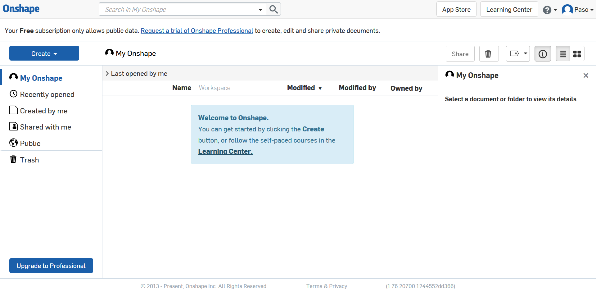
Click on Create and
Document... to start a new project.
Choose a Document name and Create public document.
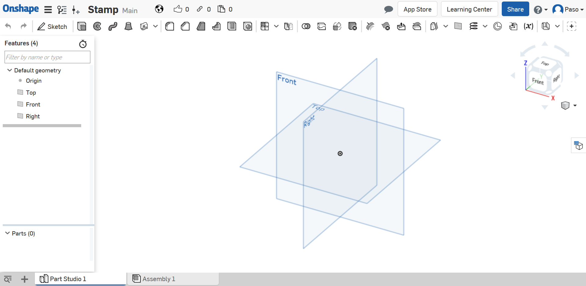
Now you can see the navbar, the toolbar, the part studio sidebar, the part window and the footer.
In this tutorial we can ignore navbar and footer.
In the toolbar you can find all available commands including Variable: this is useful to reuse the same value more than once and edit it later automatically. Click on it and edit the dialog box. Use width as Name and 30 as Value.
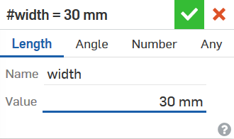
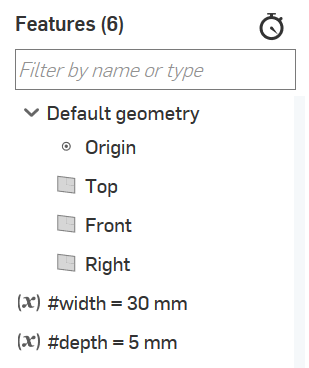
Repeat this step with depth as Name and 5 as Value. In part studio sidebar you can see the variables that you have added and, afterwards, all sketches and 3D functions used.
1.2 Base
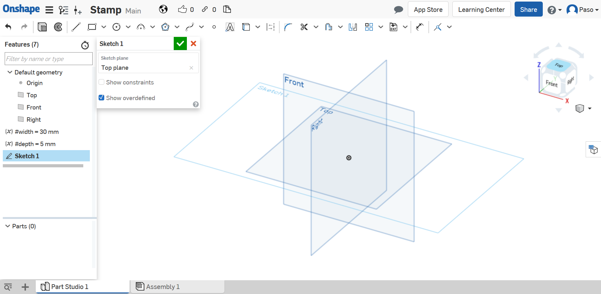
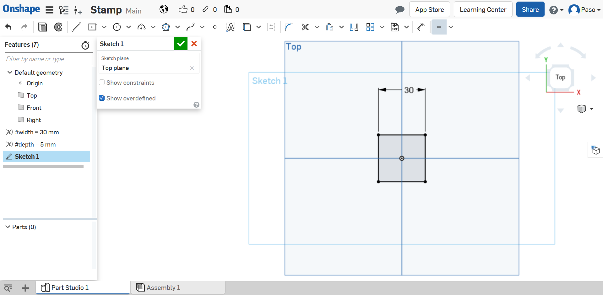
First to build a 3D figure you need to start from 2D draw, then click on Sketch and select the Top plane in the part window or the part studio sidebar. To see better what you are drawing you can change the view by clicking on a face or corner of the cube. In this case the Top face.
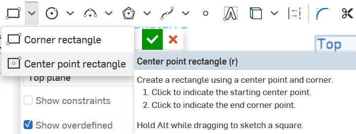
We start with a simple square: click on the down arrow near the rectangle in the toolbar and select Center point rectangle.
Select the origin point and click in a generic point to make a rectangle.
Note: when you hover on an element (a point in this case) with the mouse pointer,
it will color it orange and an icon appear nearby.
Orange rappresents the selected element and the icon the constraint that you create.
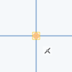
Now the rectangle is blue with a black center point. The blue means that the element is free to move, while the black means that the elemnet is fixed.
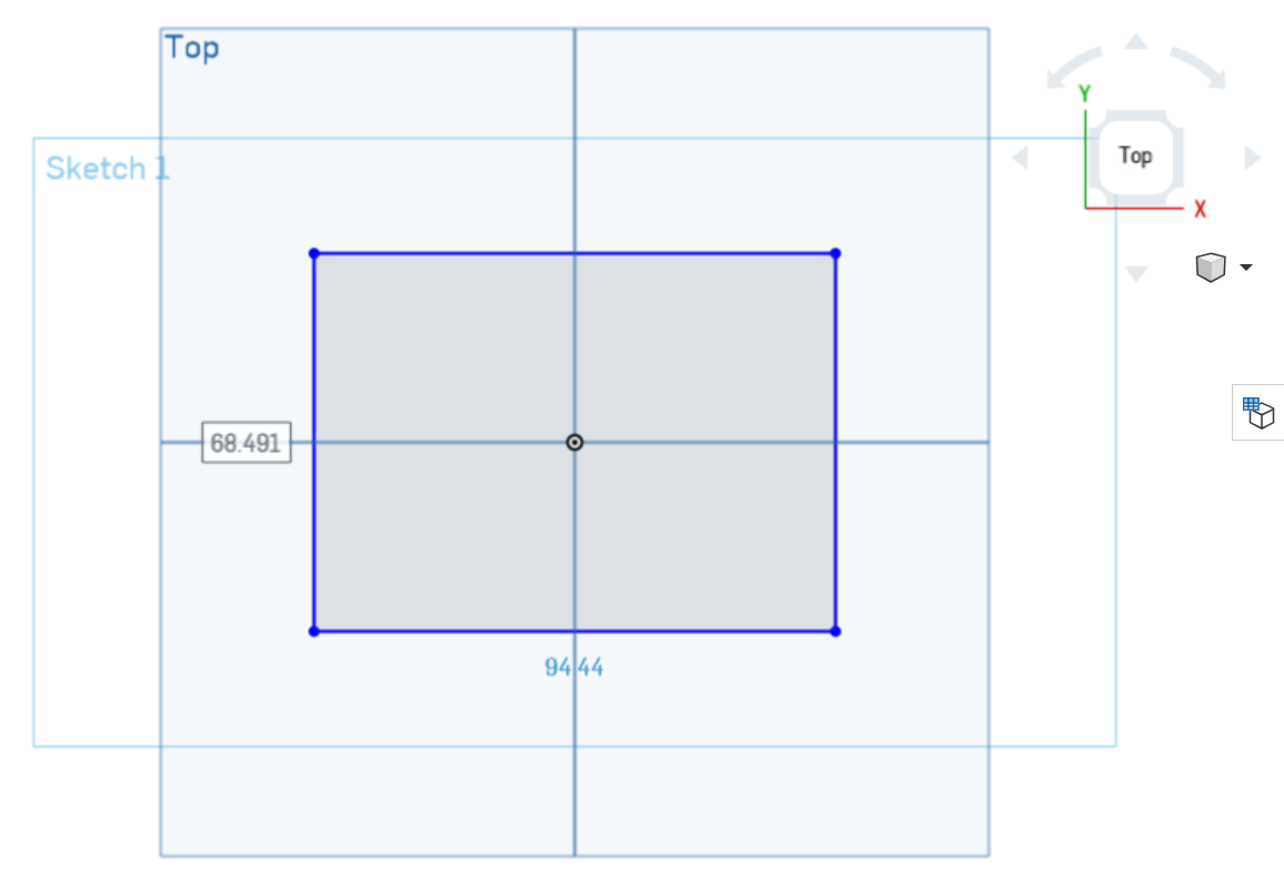
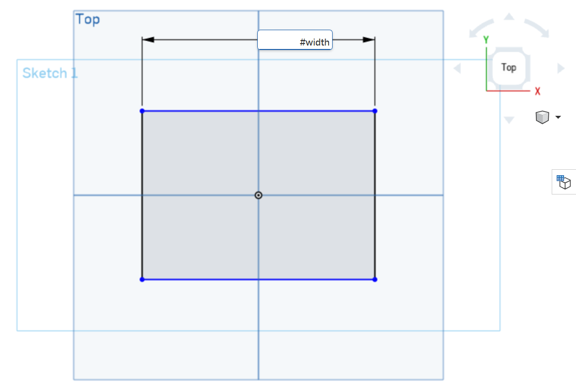
Then click on Dimension and select a side of the rectangle to quote the line. Use #width as value to connect the quote with the variable.
Note: now two rectangle sides are black and two are blue.
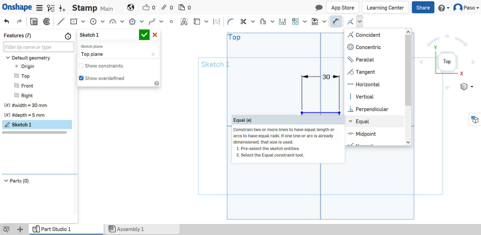
To transform the rectangle in a square click on the down arrow placed on the right side of the toolbar and
select fist the
Equal constraint and afterwards two neighbouring lines.
This is the result of the first sketch:
To turn it into a 3D figure we must Extrude, but when you click on that function it isn't possible to see its direction. Hence, we need to change view: click on the little cube on the right and Isometric.
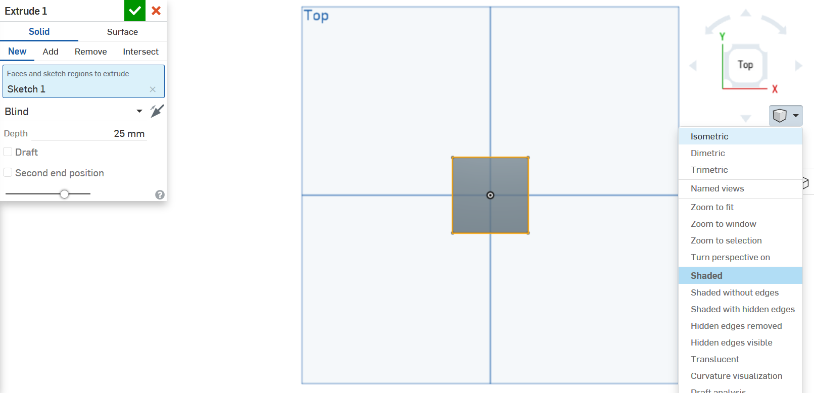
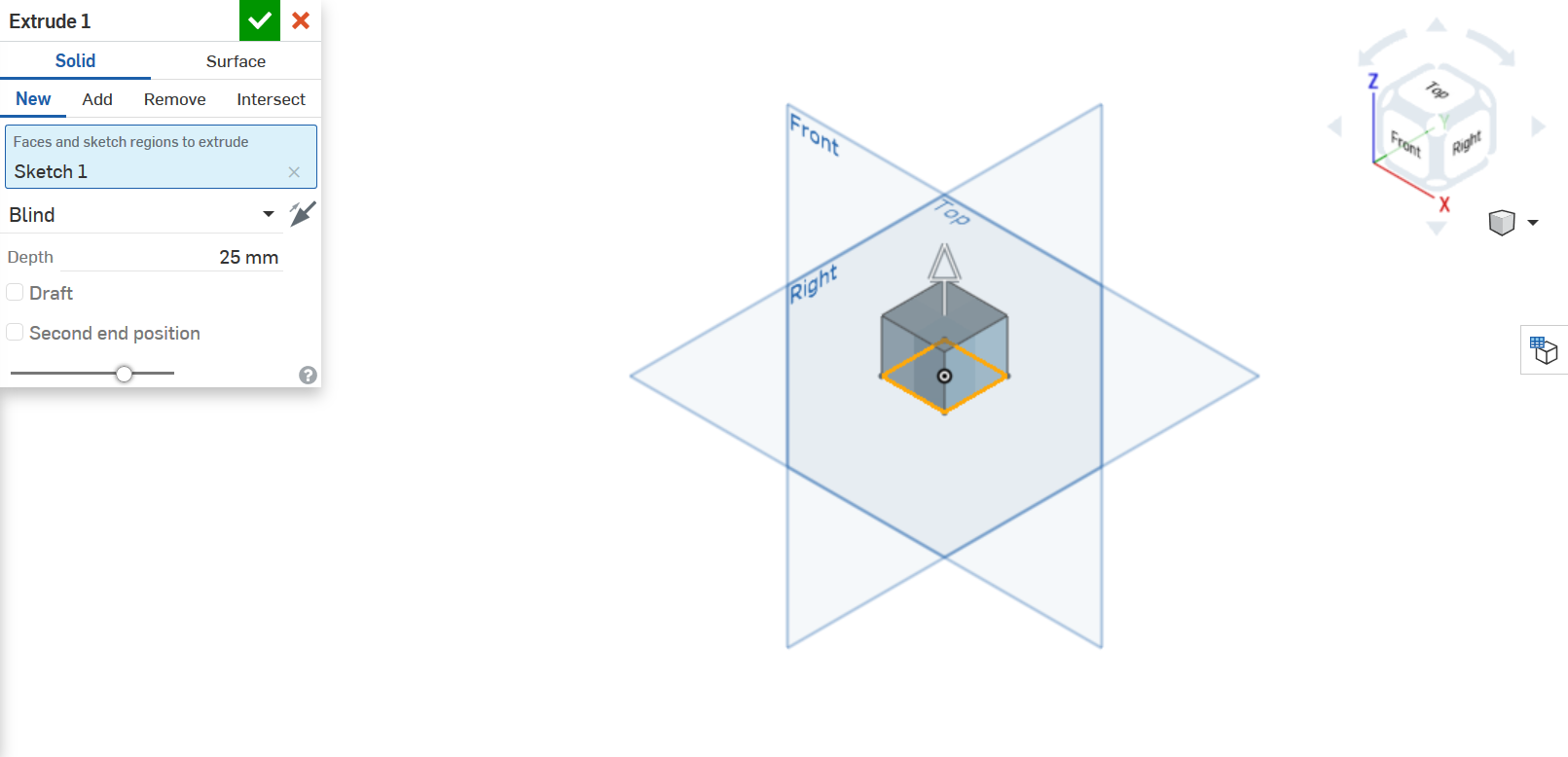
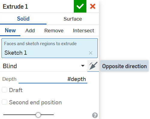
You use #depth as Depth and change direction (to simplify the next steps).
1.3 Letter
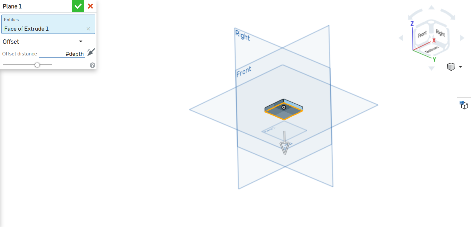
The next sketch needs a plane that does not coincide with any Default geometry or planar face. Therefore we will make a Plane, use the bottom face of the extrusion (Tips: Press and hold down the mouse wheel and move it to change the view) as Entities and #depth as Offset distance.
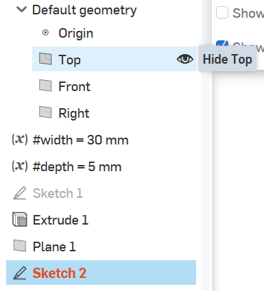
Now make a sketch on this plane, if you can't select it you can Hide planes by clicking on eye that appears when you hover the mouse on it in the part studio sidebar.
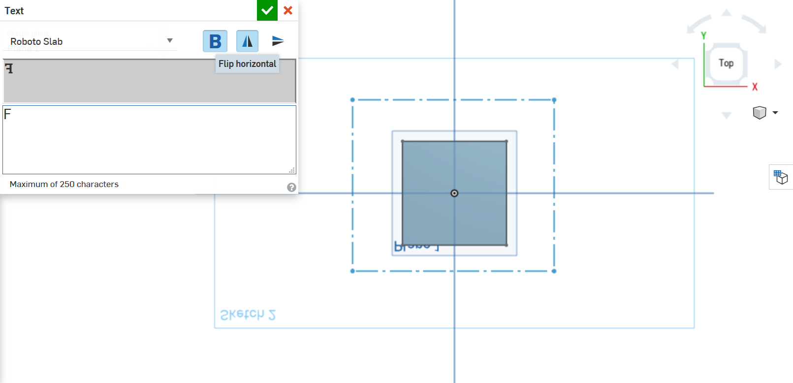
Change view and Show Sketch 1. Select Text, click on two generic points, select Roboto Slab as font, Bold, Flip horizontal and write F.
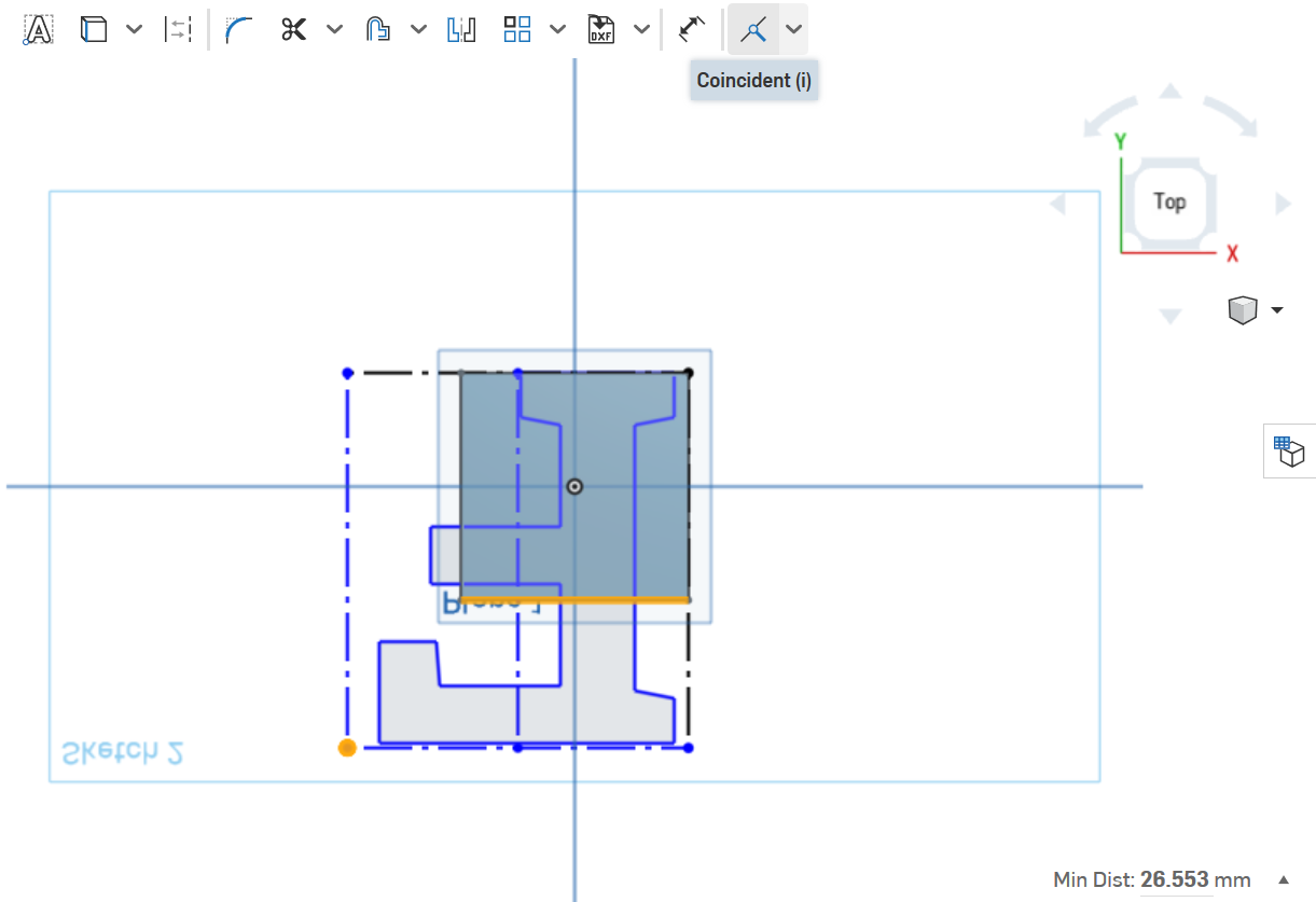
Select a top right point of Sketch 1 and top right point of letter and select Coincident as constraint. Repeat with bottom left point and bottom line (Warning: the outline rectangle is not a square like Sketch 1, hence you must not select two points).
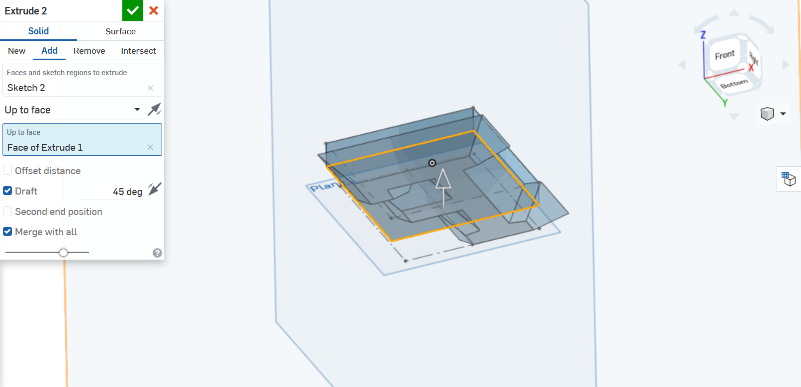
Extrude the sketch by changing End type to Up to surface and select the bottom face of Extrue 1. Add Draft and use 45 as value.
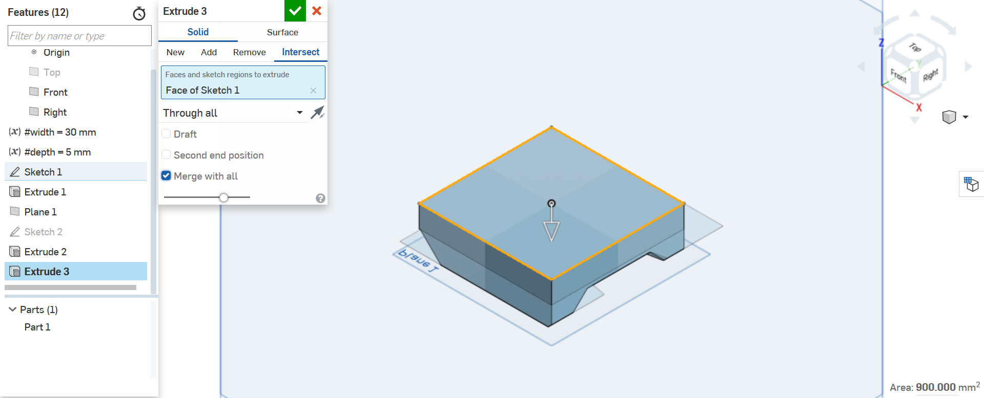
Select Sketch 1 and Extrude to reuse the same sketch, but this time select Intersect and Through all (in addition to the right direction) to remove all parts that aren't under the Sketch 1.
1.4 Handle
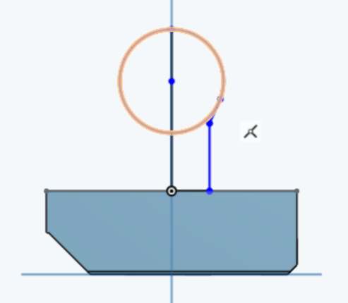
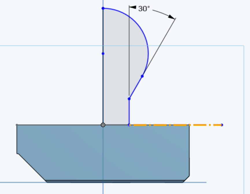
To design the handle create a new sketch on Front plane. Select Line and draw starting from Origin as in figure:
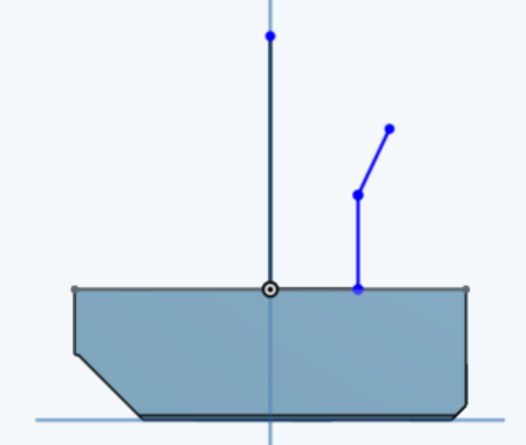
Select Center point circle and click on the long vertical line as starting point and on its end point as radius position.
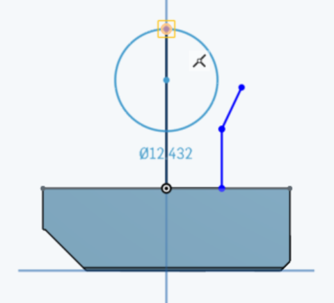
With Tangent constraint selected, click on the circle and the oblique line. Repeat with Coincident and the end point of the oblique line.
Select Trim feature and click on the left part of the circle and on the remaining section inside the area.
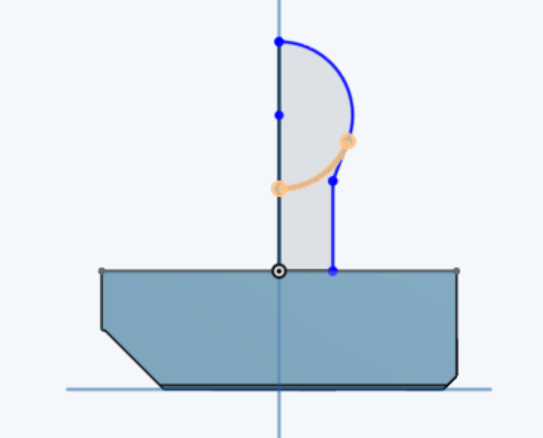
Now make Equal the horizontal line, the oblique line and the vertical line that connects them.
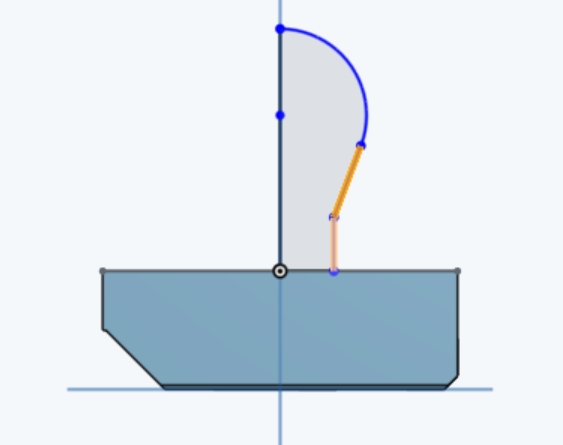
With Dimension selected, click on the vertical line and the oblique line (Note: the two lines aren't parallel, therefore you will quote the angle) and use 30deg as value.
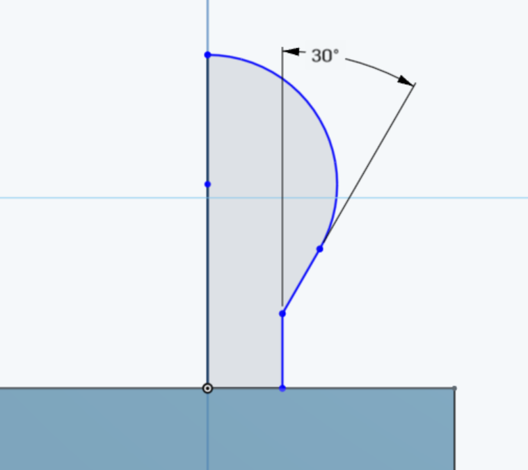
Draw a horizontal line that starts from the end point of the horizontal line already existing and ends beyond
extrusion. Select the new line and click on
Construction.
Note: construcion geometry is ignored when the sketch
region is used for features.
Make Coincident the corner of Sketch 1 and the end of construction line and Equal the two horizontal lines. Now the sketch is fixed.
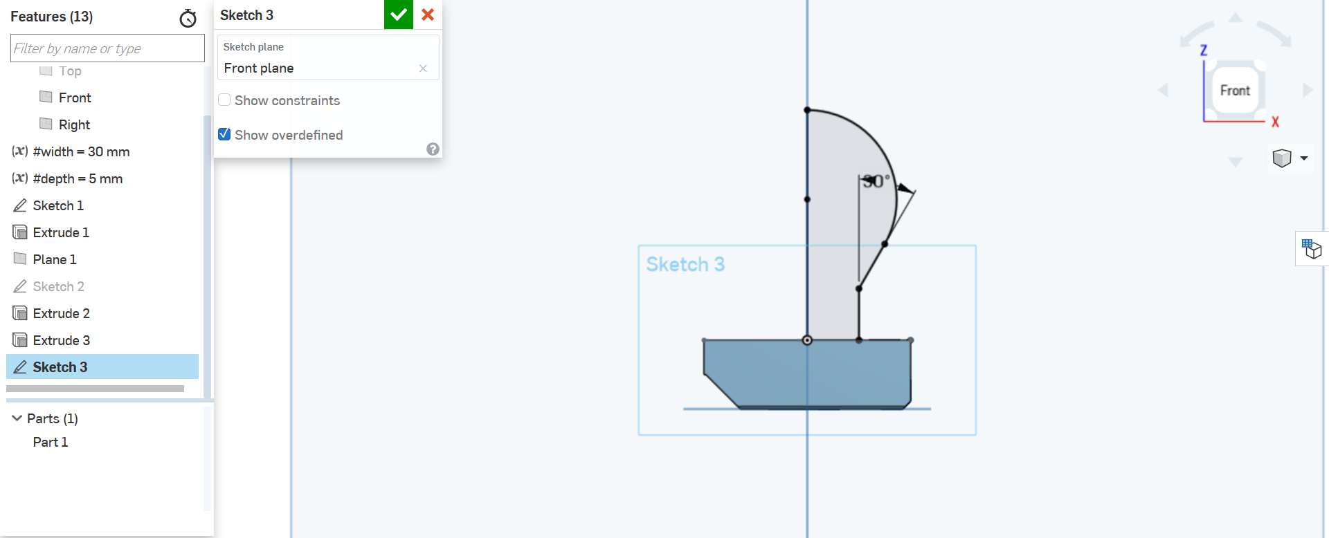
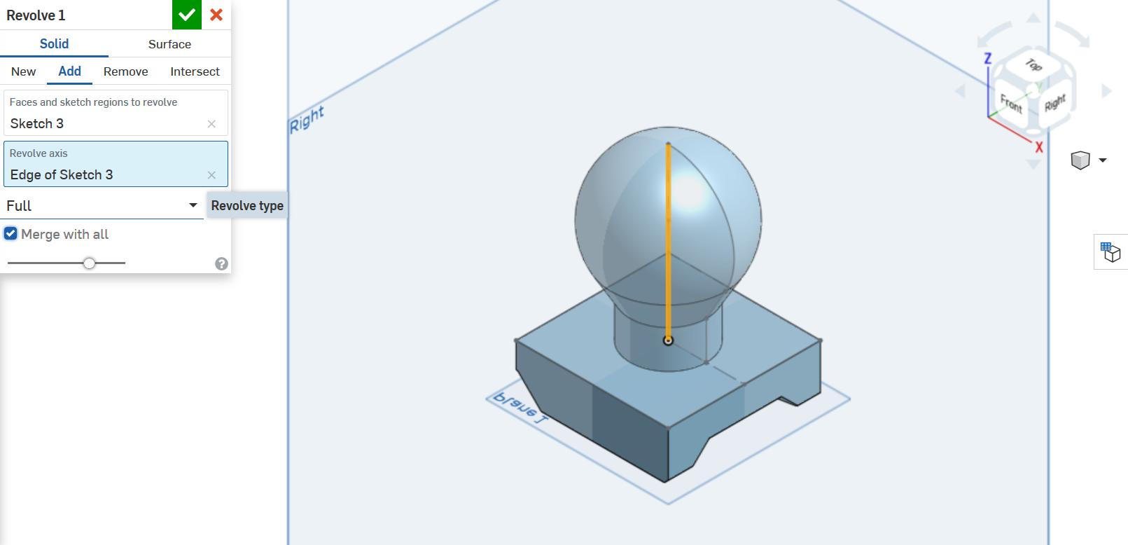
Click on Revolve and select the long vertical line as Revolve axis.
1.5 Hole
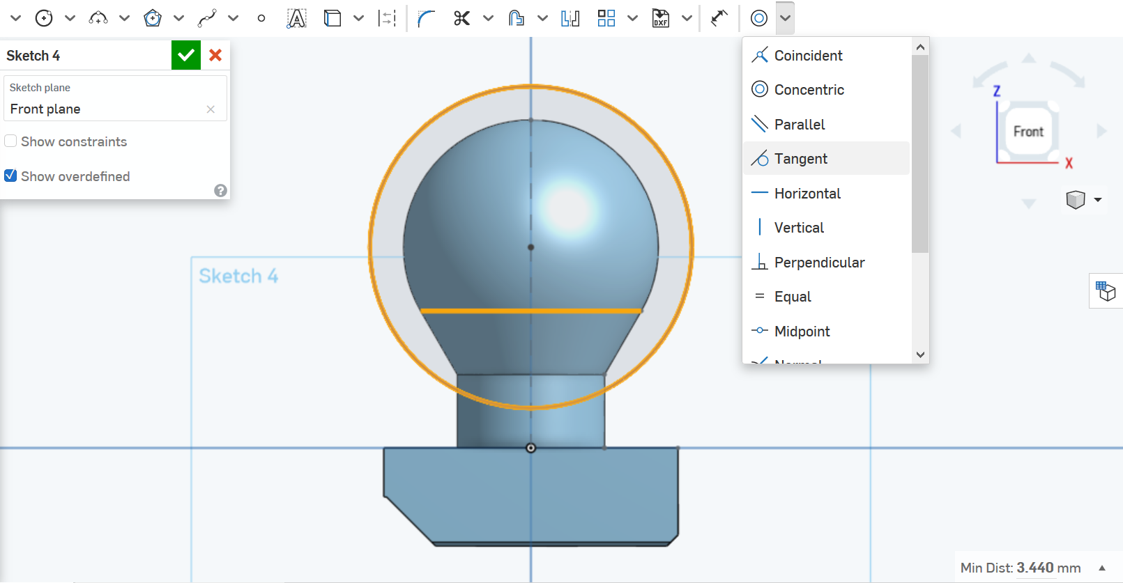
Design a hole is similar to estrusion. Start by drawing a circle on Front plane and make it Concentric with the arc of Sketch 3 (after Show Sketch 3).
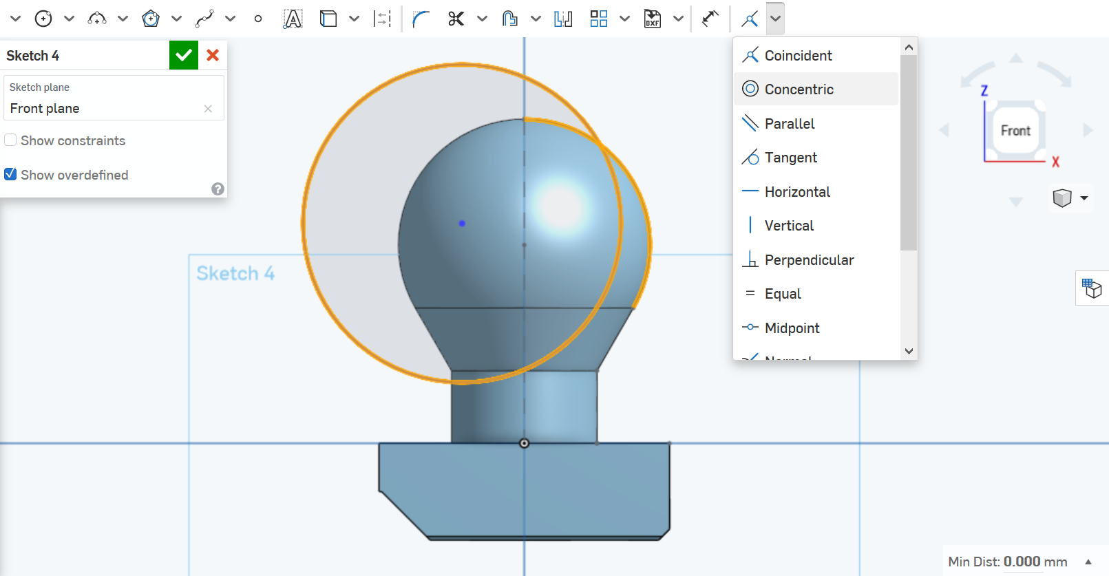
Make it Tangent to the top visible horizontal line, too.
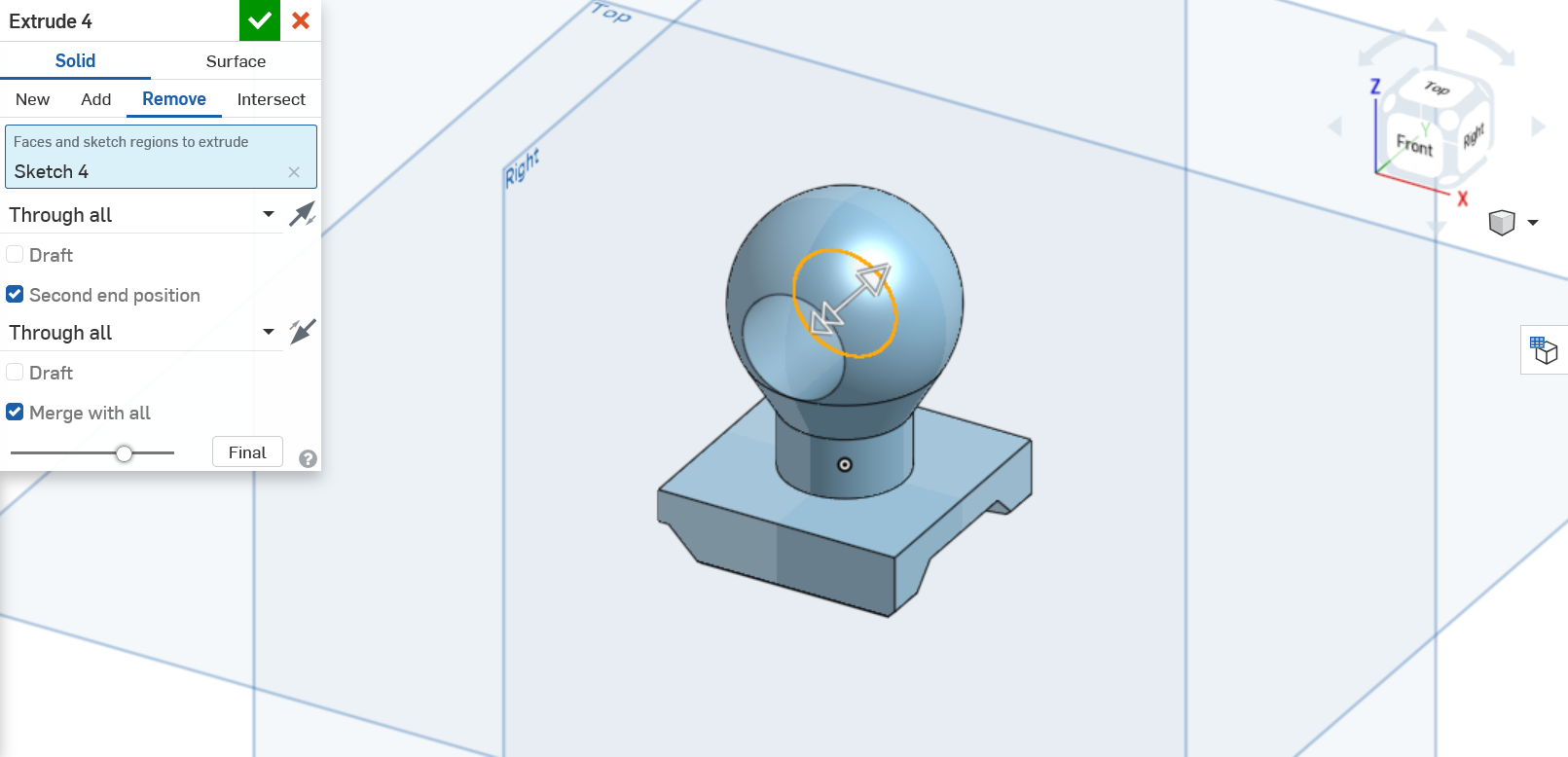
Click on Extrude and select Remove and Through all, even for Second end position.
1.6 Fillet
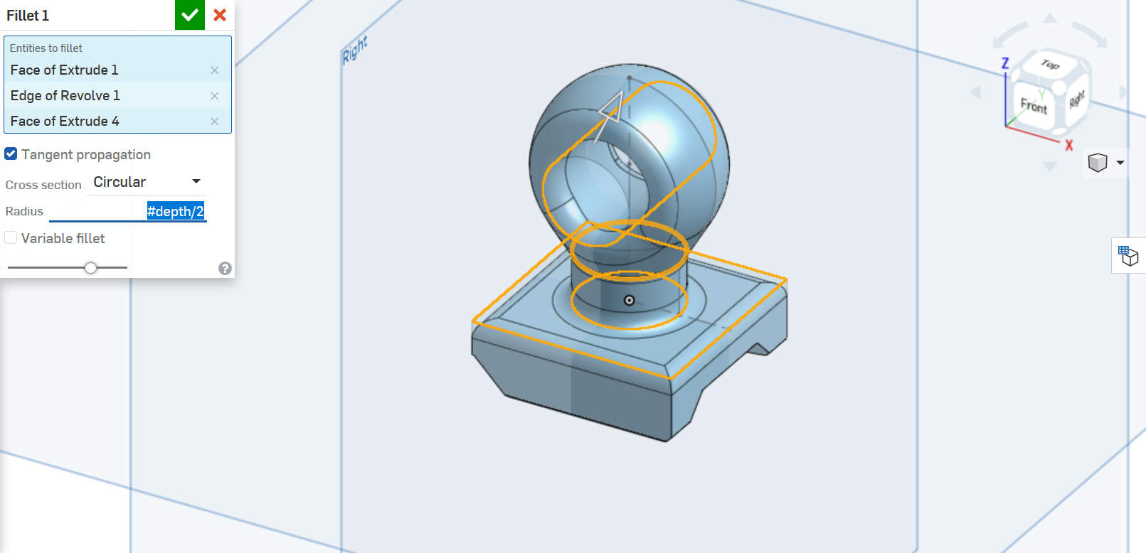
Use Fillet feature on faces and edges on top parts to round off the shapes a little bit. Use #depth/2 as Radius.
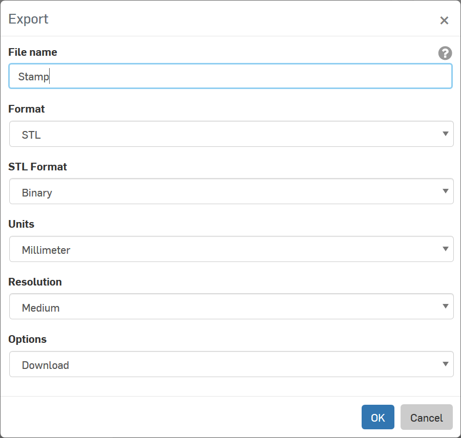
1.7 Export
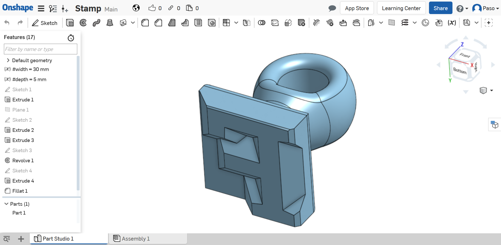
The stamp is finished!
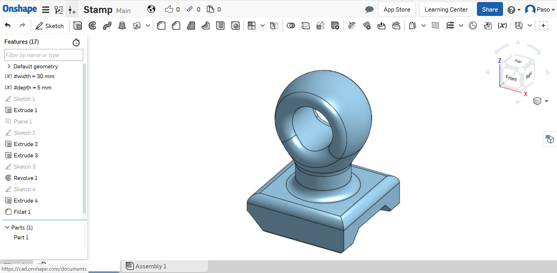
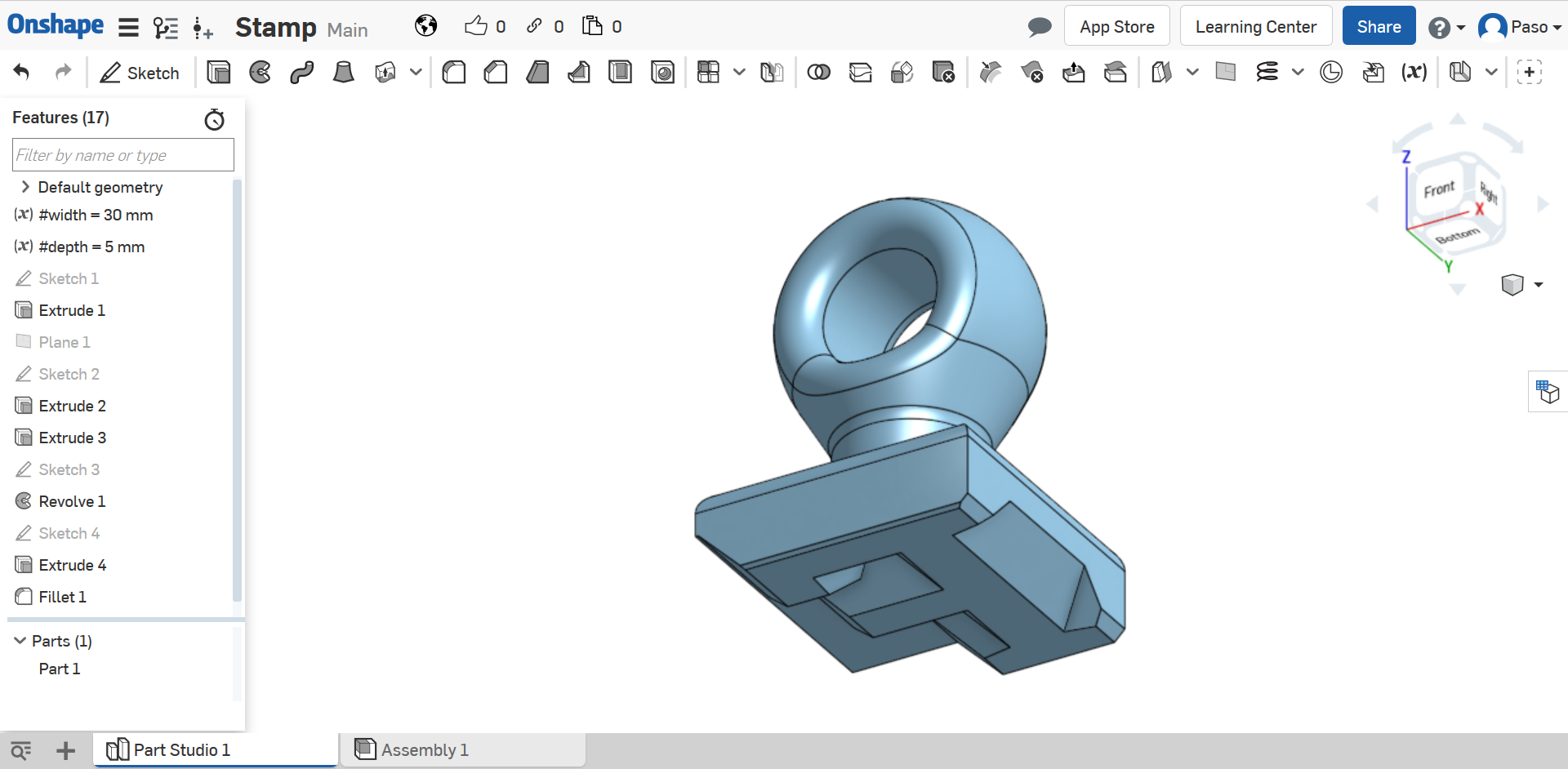
Now you can Export by clicking with the left button of your mouse on Part 1 in the part studio sidebar.
Note: choose STL as Format if you want to print it.